
Hotline
15838971872
Hotline
15838971872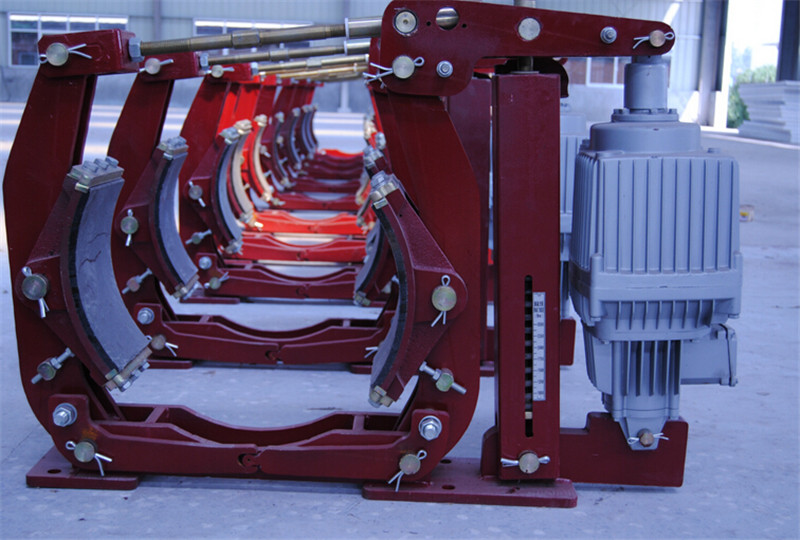
Electric hydraulic block brake pad replacementBrake linings, asbestos free brake linings, semi metal brake linings, explosion-proof brake linings, steel backed adhesive linings, Disc brake linings, clutch discs, etc. Suitable for ports, steel cranes, tower cranes, engineering machinery, drilling machinery, hydraulic machinery, and the production of various materials of automotive and power vehicle brake pads. Asbestos-free brake shoes are a new generation of brake friction materials. Traditional asbestos brake materials pose a serious threat to human health and are gradually phased out products. The new asbestos free material not only poses no harm to the human body, but also has superior performance indicators compared to asbestos brake materials. The product is mainly used for brake pads, linings, etc. of various lifting machinery and other brakes.There are two types of brake pads: one is made of asbestos rubber steel wire mesh material for the brake band, and the other is made of asbestos resin. The non asbestos brake pad and brake pad use two types: plug-in and riveted, which are safe and reliable, convenient to replace, and fast.Processing and production of 14010 brake bands | friction pads | brake pads | brake shoesMain products:1. YWZB, YWZ3, YWZ4, YWZ5, YWZ8, YWZ9, YWZ10, YWZ12, YWZ13 series electric hydraulic pad brakes2. YW series electric hydraulic tile brake3. YWL series electric hydraulic tile brake4. EYWZ series two-stage hydraulic block brake5. TWZ (B) series normally open operated pad brake6. JZ, MW, MWZ, ZWZA, ZWZ3, ZWZ3A series electromagnetic pad brakes7. YPZ2 series electric hydraulic arm disc brake8. YFX series electric hydraulic windproof iron wedge brake9. YLBZ series hydraulic wheel edge brake10. ED, YT1 series electric hydraulic thrusters11. BED and BYT1 series explosion-proof electric hydraulic thrusters12. TYWZ series hydraulic tile brake13. DCPZ series electromagnetic caliper disc brake14. QP12.7 series pneumatic caliper disc brake15. TYWZ2 series foot hydraulic block brake16. SE, SH, SP series failure disc protection brakes17. SBD series hydraulic failure protection disc brake18. DYT series electric hydraulic push rod electric push rodOur company adheres to serving society with high-quality products and reasonable prices, promoting the spirit of diligence, dedication, and innovation, adhering to the sales philosophy of customers, grasping high service quality and customer-centric as the long-term development strategy of the enterprise, and striving to provide customers with fast service and more high-quality products.
time:2022-03-29
More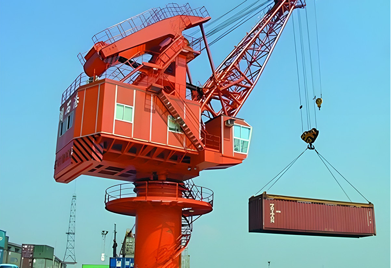
Product Introduction:Brakes:Electric hydraulic brake, electric hydraulic drum brake, electromagnetic block brake, electric hydraulic windproof iron wedge brakeSafety wind brake electromagnetic failure protection disc brake electric hydraulic arm disc brake wind electric yaw brakeWind power spindle brake Pneumatic caliper disc brake Hydraulic failure protection caliper disc brake Electromagnetic failure protection brakeHydraulic direct acting disc brake electromagnetic caliper disc brake pneumatic failure protection brake hydraulic direct acting brakeMotor disc brakePusher:Electric hydraulic thruster explosion-proof electric hydraulic thrusterBrake pads:1. Ordinary materials (resistant to high temperature of 400 degrees)2. High wear-resistant materials (4-8 times the service life of ordinary materials)3. Special wear-resistant material (8-12 times the service life of ordinary materials)4. Explosion proof materials5. Copper based material (resistant to high temperature of 800 degrees)6. Anticorrosive materialsNon standard products:1. YQP series: YQP50 YQP100 YQP160 YQP250 YQP315 YQP400 YQP3652. SB series: SB50 SB100 SB160 SB250 SB3653. YPZ series: YPZ2-I YPZ2-II YPZ2-III YPZ2-IV YPZ2-V YPZ2-VI P2-III4. QP series: QP12.7 QPL12.7-A QP25.4 QP30 QP405. YP series: YP1 YP2 YP3 YP11 YP21 YP31 YP416. Yaw series: (0.8 MW, 1.5 MW, 2 MW) DADH75 DADH80 DADH90 DADH103 DADH120 DADH1957. ADP series: ADP (H) 60 ADP (H) 90 ADP (H) 1208. SE series: 3SE (P) 4SE (P) 5SE (P) 450SE 56SE9. ST series: ST1SH ST2SH ST3SH ST4SH ST5SH ST10SH ST25SH ST25SH-A ST40SH ST3SH-A10. Wheel edge: YLBZ25-160 YLBZ40-160 YLBZ40-180 YLBZ40-200 YLBZ40-150 YLBZ63-180 YLBZ63-200YLBZ63-210 YLBZ100-20011. Copper based: FSH30 BSFA70 HB3012. Drilling rig: BSC90 ZWPS65-113. Wind power high-speed shaft: (0.8 MW, 1.5 MW, 2 MW)According to your needs, choose temperature resistance, wear resistance, select materials, provide drawings, or provide technical requirements to design friction coefficients according to production requirements.The braking force is generated by a set of disc springs that apply force to two friction plates through transmission.When the released energy disappears or a mechanical system malfunction is found,The release of energy in balance between brake action and braking force is achieved byGeneration: electric SE series hydraulic SH series pneumatic SP series 2 kinds of fail safe disc brakesA: Working brake, allowing high-frequency braking. High braking force, low maintenance costs, automatic repair of worn padsCompensation device with short response time. Large installation tolerance: brake disc end face runout, large value0.2mm. The verticality deviation of the base relative to the disc, with a maximum value of 4% o. Large deviation of Centre-to-centre distance of brake disc relative to base2.5mm. This series includes the following types of brakes:561SE 560SE 56SE 5SE 450SE 4SE 3SE brakes. Electromagnetic release. An ESE/ESP electronic control box is required for operation. 5SH 450SH 4SH 3SH 904SH brake. Hydraulic release. A hydraulic station is required for operation.5SP 450SP 4SP 3SP brake. Pneumatic release. B: Maintain and emergency brakes: With high braking force, just like various brakes. In case of overspeed detection, useAs an emergency brake, the response time of the static brake is short under normal circumstances. Manual adjustment device with pad wear.Large installation tolerance:Brake disc end face runout: maximum 0.2mm. The verticality deviation of the base relative to the disk is 4%. Installation dimensions: refer to the data sheet.This series includes a series of types of brakes:All SE series. Electromagnetic release. Equipped with electronic control box ESE/ESP during operation. All SH series are mainly ST series. Hydraulic release. Equipped with a hydraulic station during operation. All SP series. Pneumatic release.Direct acting brake:The braking force is generated by the following methods: hydraulic or pneumatic current hydraulic ADH series pneumatic ADP series electric ADE series uses a pressure control device to adjust and control the corresponding pressure to generate braking force to meet the usage requirements.Some brakes can be equipped with an automatic adjustment device for pad wear and a pad reset system.Brake pad:The brake pad is asbestos free:M-type gaskets are used for dynamic and high-speed applications. Type A gaskets are used for static or very low speeds.Other:According to different user requirements, the following devices can be installed:Pad wear display, brake display, manual release display.
time:2022-03-29
More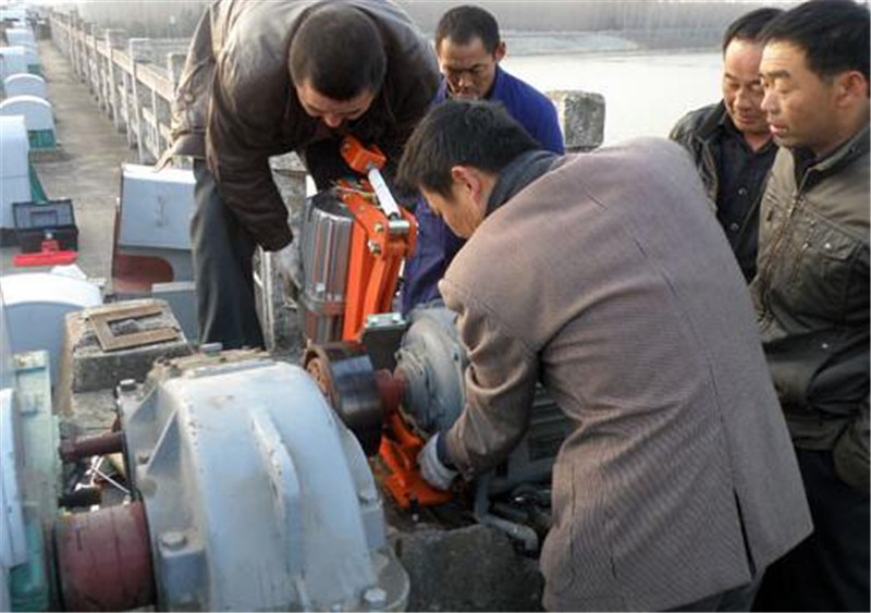
Installation method for brake wheel coupling of electric hydraulic brakeThe alignment of the coupling is divided into four steps. Now let's talk about it in detail.1. Radial alignment of couplingWhen aligning the coupling, the vertical direction should be adjusted first. The thickness of the front and rear foot pads can be calculated using three-point detection data to detect the offset of the two axes. The diameter of the outer edge of the movable end coupling plus the distance from the outer edge of the coupling to the center of the axial dial indicator rod hole; The distance from the end face of the movable end coupling to the center of the movable end front foot bolt; The distance between the center of the movable end front and rear foot bolts. From the above data, it can be seen that the thickness of the front and rear foot pads. If the motor is higher than the fixed end, the gasket should be reduced; If the motor is lower than the fixed end, a gasket should be added.After adjusting the vertical direction, the detection data at each point has changed, and it should be reset to zero at point 1, and the data at points 2 and 3 should be re measured. After adjustment, simply check whether the sum is within the allowable error range.2. Coupling principle alignmentThe projection of the movable end face circle of the motor on the fixed end face is approximated as a circle, as the distance from the movable end center to the fixed end face remains unchanged. If you want to meet both requirements, the movable end axis and the fixed end axis are definitely on the same line, which is just an ideal alignment state. When actually aligning, set the allowable error first. When the error generated during alignment is within the allowable error range, the alignment ends. In many situations, the lower detection point of the pump cannot be detected, and alignment work will not be possible.3. Three point marking method alignment steps(1) Fix the magnetic fixing seat, measuring rod, and dial indicator on the coupling of the fixed end and the movable end respectively; (2) Turn the axis to the 1 point position and reset the two dial indicators to zero; (3) Turn the axis to the 2 o'clock position again and read the data; (4) Turn the axis to the 3 o'clock position again and read the data; (5) Calculate separately (6) Loosen the front and rear foot bolts of the motor, place thick washers on the front and rear feet of the motor, move the motor as close as possible to the two couplings, then tighten the front and rear foot bolts of the motor, reset the two dial indicators at point 1, read the data at points 2 and 3, and compare with the set allowable error value. If the accuracy requirements are not met, repeat steps 2-6 above; (7) After step 6 is met, slightly loosen the front and rear foot bolts of the motor, keep the dial indicator at 3 o'clock position, and use a copper rod to tap the front and rear feet of the movable end, as well as the middle of the movable end, to align horizontally until it is within the allowable error range; (8) After step 7 is met, tighten the front and rear anchor bolts of the movable end, and the alignment is completed.4. Axial alignment of couplingHorizontal alignment does not require the calculation of the front and rear feet of the movable end. The axial and radial dial indicators are reset at 1 point, and the readings of the axial and radial dial indicators are taken at 3 points. The movable end is then tapped with a copper rod to adjust the axis. Firstly, observe the reading of the axial dial indicator, and use a copper rod to tap the front and rear feet of the movable end to adjust the axial reading at the 3-point position to half of the original value. Observe the reading of the radial dial indicator again, tap the middle of the movable end with a copper rod, and adjust the radial reading at the 3 point position to half of the original value. This requires repeated adjustments. The adjustment results should be within the allowable error range.Measures for diaphragm coupling device: Before the diaphragm coupling device is installed, the end faces of both shafts should be cleaned and the common conditions such as key grooves on the end faces should be reflected; In the future, if the diaphragm coupling device operates normally for one shift, it is necessary to reflect on all screws; In order to avoid fretting wear of the diaphragm during high-speed operation, resulting in micro cracks in the diaphragm bolt holes and damage, solid smooth agents such as Molybdenum disulfide can be applied between the diaphragms or the surface of the diaphragm can be treated with anti-wear coating. High speed diaphragm coupling; It is necessary to prevent the occurrence of prolonged overloading and operational chaos; During the operation of the task, it is necessary to frequently reflect on whether the diaphragm coupling can experience abnormal phenomena. If there are abnormal phenomena, it is necessary to carry out maintenance as soon as possible; Appropriate safety protection measures must be adopted in various places where the operation of diaphragm couplings can cause personal and equipment chaos. Pay attention to the issue with the coupling device and handle it correctly to ensure the completion of installation. Regular observation, inspection, and maintenance work should be carried out to achieve practical installation.Brake specific model:YWZ, YWZ3, YWZ4, YWZ5, YWZ8, YWZ10, YWZ9, YWZ13, YW series electric hydraulic brakesYT1, ED, YTD. series electric hydraulic thrustersJZ, MW, TJ2, ZWZA, ZWZ3 series electromagnetic brakesHow to repair and pay attention to electric hydraulic brakes?service1. Master cylinder reservoir storageAttention: Do not overfill the brake fluid. Overfilling brake fluid can cause the brake fluid to overflow onto the engine exhaust components during braking system operation, which can easily cause fire and personal injury.The main cylinder reservoir is connected to the main cylinder through a conduit. The reservoir is located on the left side of the vehicle, under the hood. The main cylinder reservoir contains sufficient brake fluid, therefore, under normal conditions, the reservoir does not require maintenance. The low brake fluid sensor in the master cylinder will issue a warning when the brake fluid level is below standard.Before disassembling the reservoir cover, it is necessary to clean it to prevent dust from entering the reservoir.·Remove the rotating cover and diaphragm.·The filling amount of the reservoir must not exceed the maximum filling level.·Install the rotating cover and diaphragm.2. Replacement of the main cylinder reservoir1) Disassembly·Remove the junction box of the liquid level sensor.·Remove the outer cover of the brake reservoir. Drain the liquid from the guide sleeve.·Use a siphon to drain the brake fluid in the brake fluid tank as empty as possible.·Separate the brake master cylinder from the infusion pipe.Important precautions: Pay attention to emerging brake fluid.·Use a water guide to lift the cover of the adjacent wall and open the brake fluid tank.·Pry open the cover of the infusion pipe on the brake master cylinder.·Check if the reservoir is cracked or deformed. If necessary, replace the reservoir.·Clean the reservoir with compressed air that does not contain lubricating oil.·Dry the storage tank with compressed air that does not contain lubricating oil.2) Installation·Apply a new seal with brake pump adhesive, insert the brake master cylinder, and install the infusion pipe.·Assemble the brake reservoir with a new hex nut.The tightening torque from the brake fluid reservoir to the next wall is 3 Newton-metre.·Install the water guide and partition cover.·Connect the liquid level sensor electrical connector.3) Inspection
time:2022-03-29
More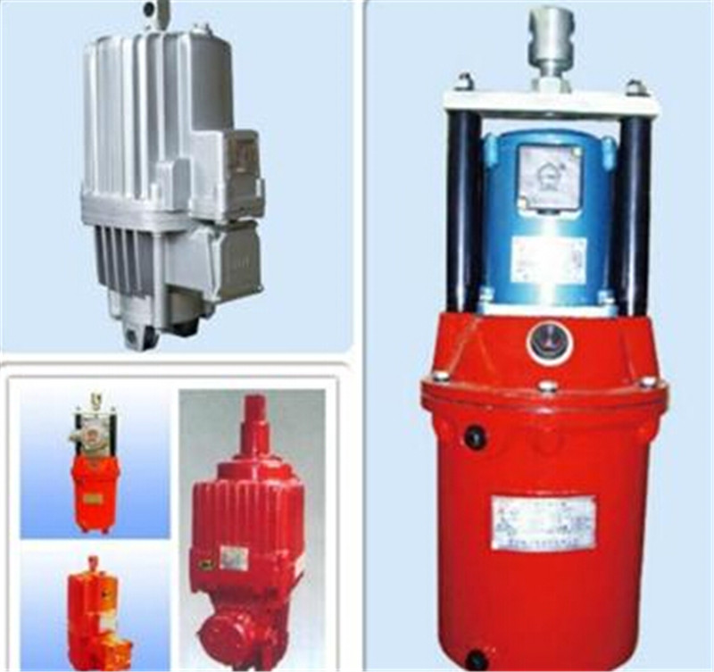
YT1-45Z/5 electric hydraulic thruster YT1-45Z/6YT1-18ZB/2, YT1-25ZB/4, YT1-25ZC/4, YT1-45Z/4YT1-45Z/5, YT1-45Z/6, YT1-90Z/6, YT1-90Z/8YT1-125Z/10, YT1-180Z/8, YT1-180Z/10YT1-180Z/12, YT1-320Z/12, YT1-320Z/20YT1-25/4, YT1-45/6, YT1-90/8, YT1-125/10, YT1-180/12YT1-18Z/2, YT1-25Z/4, YT1-25ZB/4, YT1-18/2YT1-90/6, YT1-45/5, YT1-45/4, YT1CJ-18Z/2Product model: YWZ8-400/E80 hydraulic brakeYT1CJ-45/6 hydraulic thruster YWZ-200/25 YWZB-300/45YW500-E201YW Hydraulic BrakeYWZ3B-710/180YWZ3 series hydraulic brakeTJ2-200/200 Electromagnetic BrakeYWZ10-630/201 Hydraulic BrakeMYT3-70 Hydraulic PusherMWZ315-630 Electromagnetic Block BrakeYWZ9-250/50 hydraulic brakeBED301/6 explosion-proof hydraulic thruster YW500-E121YW hydraulic brakeYWZ12-500/121S hydraulic brakeYWZ9-250/E50 hydraulic brakeYWZ5-500/121 hydraulic brakeYWZ4B-400/90YWZ4 hydraulic brakeYWZ3B-250/25YWZ3 series hydraulic brakeYWZ2-300/30YWZ series hydraulic brakeMYT3-80 Hydraulic PusherMYTD2-1250/50 hydraulic thrusterED-70/5 hydraulic thruster YW-500/201 hydraulic brakeYWK250-300YWK electric hydraulic brakeTJ2A-300 energy-saving electromagnetic block brakeHydraulic push rod brakeED-301/12 hydraulic thrusterYWZ-150/25YWZ series hydraulic brakeYWZ4-200/30YWZ4 hydraulic brakeYWZ5-630/E201 Hydraulic BrakeYWZ10-630/121 hydraulic brakeYWB-710/301 Hydraulic Brake ED-1250/120 Hydraulic Pusher_ ZWZ3-500/500ZWZ3-400/400YW630-E1250YW Hydraulic BrakeYWZ10-630/E121 Hydraulic BrakeYWZ5-250/E23 Hydraulic BrakeYWZ3B-160/25YWZ3 series hydraulic brakeMYTD2-2000/120 Hydraulic PusherYT1CJ-45Z/6 hydraulic thrusterJCZ-300/25H electromagnetic brakeYWP-400/121 Hydraulic Brake
time:2022-03-29
More
Brake product modelElectric hydraulic brakeYWZB YWZ3B YWZ4B YWZ5 YWZ8 YWZ9 YWZ12 YWZ13 YW YWL TYWZ2 YWPElectromagnetic block brakeJZ (TJ2A) MW (Z) ZWZAZWZ2 ZWZ3ADCW3Electromagnetic failure protection disc brake5SE 561SE 560SE 56SEDCPZ12.7 4SE 3SE ST1SE ST2SE 450SEHydraulic failure protection disc brake5SH 4SH 3SH 450SH ST1SH ST2SH ST3SH ST4SHSB (YQP) SBDST5SH ST10SHST16SHST25SHST25SH-AST40SH904SHSBBElectro hydraulic arm disc brakeYPZ2 I, II, IIIYPZ2 IV, V, VIPneumatic caliper disc brake QP12.7 5SP4SP3SP450SPPDADP60M-ADP61M-ADP62MHydraulic direct acting disc brake DADH75ADH60ADH90ADH120DADH80DADH90DADH120DADH103DADH195Electric hydraulic thrusterYT1 EdMYT1 hydraulic thruster motor modelBO62Z YDT80-2 ASF82A ASF102A B112Z A028012A028022 three-phase asynchronous motorExplosion proof electric hydraulic thrusterBYT1 BEDED201/6, ED301/6, ED50/12, ED80/12ED201/6, ED301/6, ED50/12, ED80/12ED201/6, ED301/6, ED50/12, ED80/12ED201/6, ED301/6, ED50/12, ED80/12ED23/5, ED30/5, ED40/4, ED50/6 electric hydraulic thrusters, hydraulic thruster manufacturers, hydraulic thruster pricesED70/5, ED80/6, ED100/6, ED121/6 electric hydraulic thrusters, hydraulic thruster manufacturers, hydraulic thruster pricesED201/6, ED301/6, ED50/12, ED80/12 electric hydraulic thrusters, hydraulic thruster manufacturers, hydraulic thruster pricesED121/12, ED201/12, ED301/12, ED450/12 electric hydraulic thrusters, hydraulic thruster manufacturers, hydraulic thruster pricesED630/12, ED121/8, ED201/8, ED301/8, ED450/8 electric hydraulic thrusters, hydraulic thruster manufacturers, hydraulic thruster pricesProduct model: YWZ8-400/E80 hydraulic brakeYT1CJ-45/6 hydraulic thrusterYW500-E201YW Hydraulic BrakeYWZ3B-710/180YWZ3 series hydraulic brakeTJ2-200/200 Electromagnetic BrakeYWZ10-630/201 Hydraulic BrakeMYT3-70 Hydraulic PusherMWZ315-630 Electromagnetic Block BrakeYWZ9-250/50 hydraulic brakeBED301/6 explosion-proof hydraulic thruster YW500-E121YW hydraulic brakeYWZ12-500/121S hydraulic brakeYWZ9-250/E50 hydraulic brakeYWZ5-500/121 hydraulic brakeYWZ4B-400/90YWZ4 hydraulic brakeYWZ3B-250/25YWZ3 series hydraulic brakeYWZ2-300/30YWZ series hydraulic brakeMYT3-80 Hydraulic PusherMYTD2-1250/50 hydraulic thrusterED-70/5 hydraulic thruster YW-500/201 hydraulic brakeYWK250-300YWK electric hydraulic brakeTJ2A-300 energy-saving electromagnetic block brakeHydraulic push rod brakeED-301/12 hydraulic thrusterYWZ-150/25YWZ series hydraulic brakeYWZ4-200/30YWZ4 hydraulic brakeYWZ5-630/E201 Hydraulic BrakeYWZ10-630/121 hydraulic brakeYWB-710/301 Hydraulic Brake ED-1250/120 Hydraulic Pusher_ ZWZ3-500/500ZWZ3-400/400YW630-E1250YW Hydraulic BrakeYWZ10-630/E121 Hydraulic BrakeYWZ5-250/E23 Hydraulic BrakeYWZ3B-160/25YWZ3 series hydraulic brakeMYTD2-2000/120 Hydraulic PusherYT1CJ-45Z/6 hydraulic thrusterJCZ-300/25H electromagnetic brakeYWP-400/121 Hydraulic Brake
time:2022-03-29
More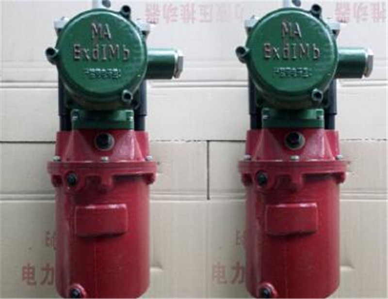
Where can I sell high-quality electric hydraulic thrustersED series electric hydraulic thrustersED-23/5; ED-30/5; ED-50/6; ED-80/6; ED-121/6; ED-201/6; ED-301/6; ED-50/12; ED-80/12; ED-121/12; ED-201/12; ED-301/12; ED-630/12YT1 series electric hydraulic thrusterYT1-18ZB/2; YT1-25ZB/4; YT1-45Z/5; YT1-90Z/8; YT1-125Z/10; YT1-180Z/10; YT1-320Z/12; YT1-320Z/20; YT1-25/4; YT1-45/6; YT1-90/8; YT1-180/12MYT1 series electric hydraulic thrusterMYT1-18ZB/2; MYT1-25ZB/4; MYT1-45Z/5; MYT1-90Z/8; MYT1-125Z/10; MYT1-180Z/10; MYT1-320Z/12; MYT1-320Z/20; MYT1-25/4; MYT1-45/6; MYT1-90/8; MYT1-180/12YTD series electric hydraulic thrusterYTD-300-60, YTD-500/60, YTD800-60, YTD1250-600, YTD2000-600, YTD3000-600The above electric hydraulic thrusters are matched with brake models: YWZ, YWZB, YWZ2, YWZ3B, YWZ4B, YWZ5, YWZ8, YWZ9, YWZ13, YW, YWL and other series of hydraulic brakes.Manufacturer of Jiaozuo electric hydraulic thrusterThe pump is composed of components such as rotor 1, stator 2, blades 3, oil distribution plate, and end cover; The inner surface of the stator is a cylindrical hole; There is eccentricity between the rotor and stator; The blades can slide flexibly in the slots of the rotor. Under the centrifugal force during rotor rotation and the pressure oil flowing into the blade root, the top of the blades is tightly attached to the inner surface of the stator, forming sealed working cavities between two adjacent blades, oil distribution plates, stator, and rotor; When the rotor rotates in a counterclockwise direction, the blade on the right side of the figure extends outward, and the volume of the sealing working chamber gradually increases, creating a vacuum. Therefore, oil is sucked in through the suction port 6 and the window on the oil distribution plate 5; On the left side of the figure; The blades retract inward, and the volume of the sealing chamber gradually decreases. The oil in the sealing chamber is pressed out through another window of the oil distribution plate and the oil pressure port 1 and output to the system; This type of pump absorbs and presses oil once during each rotation of the rotor, hence it is called a single acting pump; The rotor is subjected to radial hydraulic imbalance force, so it is also known as a non balanced pump, and its bearing load is relatively large; By changing the eccentricity between the stator and rotor, the displacement of the pump can be changed, so these pumps are variable displacement pumps.
time:2022-03-29
More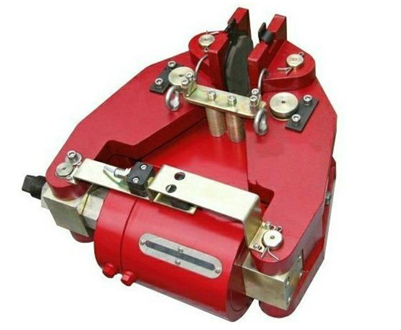
Brake specific model:YT1, ED, YTD. series electric hydraulic thrustersJZ, MW, TJ2, ZWZA, ZWZ3 series electromagnetic brakesYWZ, YWZ3, YWZ4, YWZ5, YWZ8, YWZ10, YWZ9, YWZ13, YW series electric hydraulic brakesQP, CQP series pneumatic caliper disc brakeDCPZ series electromagnetic caliper disc brakeYPZ2 YPZ3 series arm disc brakeSBD SB Series Safety BrakesSH, ST series hydraulic failure protection brakeDADH series hydraulic direct acting brakeSE series electromagnetic failure protection brakeSP series pneumatic failure protection brakeYFX, YDGZ, YLBZ, Series Windproof BrakesDP series motor disc brakeCustomized various brakes, thrusters, friction pads, brake wheels, brake discs, and customized non-standard brakes according to user needs.
time:2022-03-29
More
YFX-630/80 Electric Hydraulic Windproof Wedge BrakeYFX-500/80 YFX-550/80 YFX-600/80 YFX-630/80 YFX-700/80 YFX-710/80 YFX-800/80YFX electric hydraulic windproof iron wedge brake is mainly used as a gantry crane, loading and unloading bridge, and gate seat for outdoor use in ports, docks, railways, and other areasWindproof devices for rail mounted cranes such as cranes in working conditions, which can also work together with other devices for the safety of cranes in non working conditionsWind braking measures. When the crane encounters strong winds during operation, it can be safely braked.2.1 Environmental temperature: -25 ° C~+50 ° C (please refer to the user manual of the thruster).2.2 There should be no flammable, explosive, or corrosive gases in the surrounding working environment, and the relative humidity of the air should not exceed 90%.2.3 Generally used for three-phase AC380V, 50Hz (see thruster nameplate).2.3 The altitude of the location of use shall comply with the GB/T755-2000 standard.2.4 Technical parameters: Wind resistance capacity of a single windproof iron wedge brake (converted into horizontal force) F:F=fxN wheel (N wheel is wheel pressure, f is friction coefficient=0.46)The FX series windproof iron wedge brake consists of two main parts: a brake frame and a matched Ed electric hydraulic thruster. When the thruster is onElectricity, its push rod quickly rises and lifts the iron wedge through a lever and transmission mechanism to ensure normal operation of the crane; When the thruster is powered off, the thrusterThe push rod is subjected to spring force and the iron wedge is placed on the steel rail through a lever. Wedge the wheels to ensure safety during a sudden stormProtective effect. (Note: When the wheel presses against the iron wedge, the iron wedge cannot be lifted. At this time, the crane should be started in the opposite direction, and the iron wedge should be used for lifting.)After lifting, the crane can resume normal operation4.1 Installation: Loosen the windproof iron wedge first with four bolts through 4-? L (as shown in the above figure) is connected to the crane.4.2 Adjustment: After installation, adjust the position of the fixing plate so that the iron wedge is placed flat and straight on the rail, and ensure the lifting height of the thruster h1It is 8mm (at this time, the working state of the windproof iron wedge brake is in a wedged state, where the iron wedge is tightly against the wheel. If it is less than 8mm, it should be fixed byThe long hole on the fixed plate moves the brake down as a whole, and vice versa, moves the brake up as a whole Tighten the installation bolts. Then turn on the power or use theThe manual device lifts the iron wedge to a high position, adjusts the bolt (4) so that the distance between the iron wedge and the steel rail is not less than 16mm, and does not collide with the wheel,At the same time, ensure that the installation length of the spring (6) is between 26-28 millimeters (the free length of the spring is 30mm). Iron wedge during power outagePlace it on the steel rail at a distance of approximately 50mm from the wheel. Afterwards, use the lowering valve s of the thruster to adjust the lowering speed of the iron wedge (first unscrew the antiDust cover, screw in the adjustment screw to slow down the descent speed, otherwise the descent speed will increase. It is recommended to delay the iron wedge pressing on the steel rail for 6 seconds after the brake is powered offOn.), After adjustment, all iron wedges should fall on the rail simultaneously after power outage.Consultation hotline 158389718725.1 Regularly check the working condition of the brakeDuring inspection, the following items should be emphasized:The distance between the iron wedge and the steel rail should not be less than 16mm.Check whether the components of the brake move normally and whether the adjusting nuts are tightened.Whether the thruster works normally, whether the hydraulic oil is sufficient, whether there is oil leakage and oil seepage, and whether the insulation of the incoming wire is good.The wear of the pin and spindle exceeds 5% of the original diameter or the ovality exceeds 0.5mm, which should be updated.Whether the friction block is normally attached to the rail, whether the friction surface is in good condition, and whether there are greasy and dirty marksWhen the tooth shape is worn, an adjusting shim should be added to make the bottom surface of the friction block 1 mm higher than the ground of the iron wedge. When the tooth shape is worn more than half, it should be replaced or repairedFriction block.During maintenance, connect the power supply or use a manual device to lift the iron wedge to a high position, and take out the pin (16) from the pin hole 15 and place it in the pin hole (17)At this point, the windproof iron wedge is in the released state for maintenance purposes.6.1 As the windproof iron wedge brake operates in one direction, it needs to be installed symmetrically. So one crane should be equipped with at least four windproof iron wedge brakesOr install 8, 12, or 4N units according to actual needs (N is a constant).6.2 Pay attention to the installation position of the windproof iron wedge brake. The correct thing is that when the windproof iron wedge brake in a certain direction acts, its point of action should beAfter the center of gravity of the crane (relative to the direction of crane operation). If some are in front and some are behind, the descent on the thruster should be adjustedThe valve causes the windproof iron wedge brake behind the center of gravity of the crane to brake first.When the windproof iron wedge brake operates normally, the crane should be completely stopped before the iron wedge falls onto the track to avoid unnecessary damage to the iron wedgeImpact (excluding emergency braking), thereby extending the service life of the friction block.6.4 In the event of a sudden storm, the windproof iron wedge brake is in an emergency braking state, and the traveling mechanism of the crane should be connected to the windproof iron wedge brakeSimultaneously cutting off the power and locking the wheels provides safety protection.
time:2022-03-27
More
Supply explosion-proof electric hydraulic thruster BED301/12 BED301/6BED ED series electric hydraulic thrusters:BED30/5; BED50/6; BED80/6; BED121/6; BED201/6; BED301/6; BED50/12; BED80/12; BED121/12BED201/12; BED301/12; BED630/12Main products: electric hydraulic arm disc brake, pneumatic disc brake, hydraulic failure protection brake, electromagnetic failure protection brake, wheel edge brake, electric hydraulic wind proof iron wedge brake, ZWZ3 series electromagnetic DC drum brake, YWZB series electric hydraulic drum brake, YWZ3B series electric hydraulic drum brake, YWZ4 series electric hydraulic drum brake, YWZ5 series electric hydraulic drum brake, YWZ8 series electric hydraulic drum brake, YWZ9 series electric hydraulic drum brake, YWZ10 series electric hydraulic drum brake, YWZ13 series electric hydraulic drum brake, YWL series electric hydraulic drum brake, YWP series electric hydraulic drum brake, YW-E series electric hydraulic two-stage drum brake, YW series electric hydraulic drum brake, YW series pneumatic drum brake, ED series electric hydraulic thruster, The YT1 series electric hydraulic thrusters, BED series electric hydraulic thrusters, and BYT1 series electric hydraulic thrusters can operate up to 720 times per hour. Comply with JB/ZQ4388-86 standard;
time:2022-03-27
More
YWZB-200/25 Hydraulic Brake ManufacturerPhone 158 3897 1872Electric hydraulic brakeYWZB YWZ3B YWZ4B YWZ5 YWZ8 YWZ9 YWZ12 YWZ13 YW YWL TYWZ2 YWPElectromagnetic block brakeJZ (TJ2A) MW (Z) ZWZAZWZ2 ZWZ3ADCW3Electromagnetic failure protection disc brake5SE 561SE 560SE 56SEDCPZ12.7 4SE 3SE ST1SE ST2SE 450SEHydraulic failure protection disc brake5SH 4SH 3SH 450SH ST1SH ST2SH ST3SH ST4SHSB (YQP) SBDST5SH ST10SHST16SHST25SHST25SH-AST40SH904SHSBBElectro hydraulic arm disc brakeYPZ2 I, II, IIIYPZ2 IV, V, VIPneumatic caliper disc brake QP12.7 5SP4SP3SP450SPPDADP60M-ADP61M-ADP62MHydraulic direct acting disc brake DADH75ADH60ADH90ADH120DADH80DADH90DADH120DADH103DADH195Electric hydraulic thrusterYT1 EdMYT1 hydraulic thruster motor modelBO62Z YDT80-2 ASF82A ASF102A B112Z A028012A028022 three-phase asynchronous motorExplosion proof electric hydraulic thrusterBYT1 BEDOur company adheres to the business philosophy of "conducting oneself in the world and creating a win-win situation together". Our products now serve hundreds of large enterprises and tens of thousands of small and medium-sized enterprises in China, involving industries such as machinery, metallurgy, ports, docks, electricity, railways, water conservancy, chemical engineering, etc. We have successfully designed and manufactured specialized transmission equipment with advanced international industry standards for multiple large enterprises and many key construction projects in China. Our high-quality products and after-sales service beyond contracts have been widely recognized and praised by users. At present, our products are undertaking heavy responsibilities and serving society in multiple industries related to national construction and development.Gratitude to friends, return to society, integrity to the world, and jointly build the future. We sincerely welcome friends from all walks of life to patronize and cooperate.
time:2022-03-27
More
Specific model:YT1, ED, YTD. series electric hydraulic thrustersJZ, MW, TJ2, ZWZA, ZWZ3 series electromagnetic brakesYWZ, YWZ3, YWZ4, YWZ5, YWZ8, YWZ10, YWZ9, YWZ13, YW series electric hydraulic brakesQP, CQP series pneumatic caliper disc brakeDCPZ series electromagnetic caliper disc brakeYPZ series arm disc brakeSBD series safety brakeSH, ST series hydraulic failure protection brakeDADH series hydraulic direct acting brakeSE series electromagnetic failure protection brakeSP series pneumatic failure protection brakeYFX, YDGZ, YLBZ, Series Windproof BrakesDP series motor disc brakeCustomized various brake wheel couplings, disc brake pads, drum friction pads, brake discs, and customized non-standard brakes according to user needsYWZ-200/25, one set YWZ-300/80, one set
time:2022-03-27
More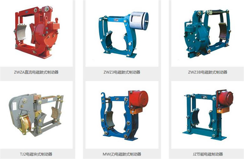
Manufacturer of dedicated electromagnetic iron block brake for hoistZWZB-400/400, ZWZB-400/500 electromagnetic brake ZWZA-315/300 electromagnetic brake ZWZA-250/300, ZWZA-315/200 electromagnetic brake ZWZA-200/300, ZWZA-250/200 electromagnetic brake ZWZA-200/100, ZWZA-200/200 electromagnetic brake ZWZA-160/100, ZWZA-160/200 electromagnetic brake TJ2A-700/700, TJ2A-800/800 electromagnetic brake TJ2A-500/500, TJ2A-600/600 electromagnetic brake TJ2A-300/300, TJ2A-400/400 electromagnetic brake TJ2A-100/100, TJ2A-200/200 electromagnetic brake JCZ400/45HA, JCZ500/45H brake JCZ300/15, JCZ300/15H brake JCZ-600/100H, JCZ200/15 brake JCZ-500/45H, JCZ-500/80H brake ZWZ2-250/300, ZWZ2-315/200 DC electromagnetic iron block brake ZWZ2-200/300, ZWZ2-250/200 DC electromagnetic iron block brake ZWZ2-160/100, ZWZ2-160/200 DC electromagnetic iron block brake ZWZ3A-800/800 DC electromagnetic iron block brake ZWZ3A-710/800, ZWZ3A-800/700 DC electromagnetic iron block brake ZWZ3A-710/600, ZWZ3A-710/700 DC electromagnetic iron block brake ZWZ3A-630/600, ZWZ3A-630/700 DC electromagnetic iron block brake ZWZ3A-500/600, ZWZ3A-630/500 DC electromagnetic iron block brake ZWZ3A-500/400 DC electromagnetic iron block brake ZWZ3A-400/400, ZWZ3A-400/500 DC electromagnetic block brake MWZ200-160, MWZ315-630 electromagnetic block brake MW630-5000, MW710-8000 electromagnetic block brake MW400-1250, MW500-2500 electromagnetic block brake MW250-315, MW315-630 electromagnetic block brake MW160-80, MW200-160 electromagnetic block brakeElectric hydraulic brakeYWZB YWZ3B YWZ4B YWZ5 YWZ8 YWZ9 YWZ12 YWZ13 YW YWL TYWZ2 YWPElectromagnetic block brakeJZ (TJ2A) MW (Z) ZWZAZWZ2 ZWZ3ADCW3Electromagnetic failure protection disc brake5SE 561SE 560SE 56SEDCPZ12.7 4SE 3SE ST1SE ST2SE 450SEHydraulic failure protection disc brake5SH 4SH 3SH 450SH ST1SH ST2SH ST3SH ST4SHSB (YQP) SBDST5SH ST10SHST16SHST25SHST25SH-AST40SH904SHSBBElectro hydraulic arm disc brakeYPZ2 I, II, IIIYPZ2 IV, V, VIPneumatic caliper disc brake QP12.7 5SP4SP3SP450SPPDADP60M-ADP61M-ADP62MHydraulic direct acting disc brake DADH75ADH60ADH90ADH120DADH80DADH90DADH120DADH103DADH195Electric hydraulic thrusterYT1 EdMYT1 hydraulic thruster motor modelBO62Z YDT80-2 ASF82A ASF102A B112Z A028012A028022 three-phase asynchronous motorExplosion proof electric hydraulic thrusterBYT1 BED
time:2022-03-27
More

CopyRight © 2026 Jiaozuo brake ICP:YuICPBei 19039306-3


